3x3x3 LED Cube Circuit
This circuit drives a 3x3x3 cube consisting of 27 white LEDs. The 4020
IC is a 14 stage binary counter and we have used 9 outputs. Each output
drives 3 white LEDs in series and we have omitted a dropper resistor as
the chip can only deliver a maximum of 15mA per output. The 4020
produces 512 different patterns before the sequence repeats and you have
to build the project to see the effects it produces on the 3D cube.
555 Amplifier Circuit
The 555 can be used as an amplifier. It operates very similar to pulse-width modulation. The component values cause the 555 to oscillate at approx 66kHz and the speaker does not respond to this high frequency. Instead it responds to the average CD value of the modulated output and demonstrates the concept of pulse-width modulation. The chip gets very hot and is only for brief demonstrations.
AUTOMATIC CURTAIN CLOSER
This circuit uses a mixture of transistors, an IC and a relay and is used to automatically open and close a pair of curtains. Using switch S3 also allows manual control, allowing curtains to be left only partially open or closed. The circuit controls a motor that is attached to a simple pulley mechanism, to move the curtains.
Automatic Operation
The circuit can be broken into three main parts; a bi-stable latch, a timer and a reversing circuit. Toggle switch S3 determines manual or automatic mode. The circuit as shown above is drawn in the automatic position and operation is as follows. The bi-stable is built around Q1 and Q2 and associated circuitry and controls relay A/2. S1 is used to open the curtains and S2 to close the curtains. At power on, a brief positive pulse is applied to the base of Q2 via C2. Q2 will be on, and activate relay A/2.
The network of C3 and R4 form a low current holding circuit for the relay. Relay A/2 is a 12V relay with a 500 ohm coil. It requires slightly less current to keep it energized than it does to operate it. Once the relay has operated, the current through the coil is reduced by R4, saving power consumption. When Q2 is off, C3 will be discharged, but when Q2 becomes active (either at switch-on or by pressing S1) capacitor C3 will charge very quickly via the relay coil. The initial charging current is sufficient to energize the relay and current flow through R4 sufficient to keep it energized.
Bike Turning Signal Circuit
This circuit can be used to indicate left and right turn on a motor-bike. Two identical circuits will be needed, one for left and one for right.
BI-POLAR LED DRIVER
Some 2-leaded LEDs produce red and green. These are called Bi-polar LEDs. This circuit alternately flashes a red/green bi-polar LED:
CAR TACHOMETER
A 555 is configured as a monostable or one shot in this project. The period of the 555 is determined by the 47k and the capacitor from pin 6 to ground (100n). Time "T" = 1.1 RC or 1.1 X 50,000 X 0.1 X10 -6 = 0.0055 or 5.5 mS (milli-seconds).The 555 receives trigger pulses from the distributor points. These are limited by the 1k and 5v zener diode. These are AC coupled to the trigger input through the 100n coupling capacitor. The 50mA meter receives pulses of current through the 200k pot to show a reading.

Integration of the current pulses produces a visible indication of the cars engine speed on the 0-1mA meter.
Supply is taken from the cars 12v system and for the 555 it is reduced to a regulated 9v by the 15 ohm resistor in conjunction with the 9v zener diode. Note: the 10u electrolytic must be placed physically as close as possible to supply pin 8.
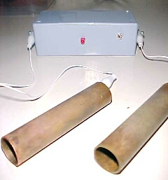
Hulda Clark's Zapper
This is the circuit for Dr. Hulda Clark's Zapper, designed in 2003. The frequency is approximately 30kHz positive offset square wave. It has a red LED light that lights up when the unit is on. Perfect for regular zapping, extended zapping and other Hulda Clark related experiments.This device is used tocure, treat and prevent any disease. It will cure anything. Simply hold the two probes (one in each hand) for 5-10 minutes then rest for 20 minutes, then repeat two more times. Do this each day and you will be cured. Here is her website: ClarkTestimonials.com Hundreds of people have been cured of everything from herpes to AIDS.
On the other side of the coin is the claim that Dr Hulda Clark is a complete quack. Here is a website called: Quackwatch. The second diagram shows the two copper tubes and the circuit in a plastic box. I am still at a loss to see how any energy can transfer from this quack machine, through the skin (50k skin resistance and 9v supply) and zap a bug in your intestine. It's a bit like saying I will kill all the mice in a haystack by stabbing the stack with a needle.
CONTINUITY TESTER
This circuit will detect low resistances and high resistances to produce a tone from the speaker.It will detect up to 200k and the circuit automatically turns off when the probes are not used.

DARK DETECTOR
When the level of light on the photo-cell decreases, the 555 is activated. Photo-cells (Photo-resistors) have a wide range of specifications. Some cells go down to 100R in full sunlight while others only go down to 1k. Some have a HIGH resistance of between 1M and others are 10M in total darkness. For this circuit, the LOW resistance (the resistance in sunlight) is the critical value.More accurately, the value for a particular level of illumination, is the critical factor. The sensitivity pot adjusts the level at which the circuit turns on and allows almost any type of photo-cell to be used.
DRIVING A BI-COLOUR LED
Some 3-leaded LEDs produce red and green. This circuit alternately flashes a red/green bi-coloured LED:
DRIVING A RELAY
The 555 will activate a relay. When pins 2 and 6 are connected as an input, the chip requires only about 1uA to activate the output. This is equivalent to a gain of about 200,000,000 (200 million) and represents about 4 stages of amplification via transistors.In the first circuit, the output will be opposite to the input. The relay can be connected "high" or "low" as show in the second diagram. One point to note: The input must be higher than 2/3V for the output to be low and below 1/3V for the output to be high. This is called HYSTERESIS and prevents any noise on the input creating "relay chatter."
NEGATIVE LOGIC
An interesting point to remember.
In the first diagram above, the relay is connected so that it is active when the output is low. This is called NEGATIVE or NEGATIVE LOGIC. It has the same reasoning as-5 - (-5) = 0.
Or in English: "I am not NOT going."
When the input is low in the first diagram, the output is HIGH and the relay is OFF. The circuitry creates two reversals and makes it easy to see that when the input is LOW, the relay is OFF.
DRIVING MANY LEDS
The 555 is capable of sinking and sourcing up to 200mA, but it gets very hot when doing this on a 12v supply.The following circuit shows the maximum number of white LEDs that can be realistically driven from a 555 and we have limited the total current to about 130mA as each LED is designed to pass about 17mA to 22mA maximum. A white LED drops a characteristic 3.2v to 3.6v and this means only 3 LEDs can be placed in series.
FLASHING RAILROAD LIGHTS
This circuit flashes two red LEDs for a model railway crossing.
KNIGHT RIDER
This circuit mimics the lights in knight rider's car. They flash one at a time chasing each other.Overview
In the Knight Rider circuit, the 555 is wired as an oscillator (Astable mode). The output of the 555 is directly connected to the input of a 4017 decade counter.
The input of the 4017 counter is called the CLOCK line. The 10 outputs Q0 to Q9 become active, one at a time, on the rising edge of the waveform from the 555. Each output can deliver about 20mA but a LED should not be connected to the output without a current-limiting resistor (100R or 220R).
Using six 3mm LEDs, the display can be placed in the front of a model car to give a very realistic effect. The same outputs can be taken to driver transistors to produce a larger version of the display.
Schematic
This circuit consumes 22mA while only delivering 7mA to each LED. The outputs are “fighting“ each other via the 100R resistors (except outputs Q0 and Q5).
Parts
1x NE555 Bipolar Timer
6x LED (Red)
8x 100 Resistor (1/4W)
2x 220 Resistor (1/4W)
1x 1K Resistor (1/4W)
1x 68K Resistor (1/4W)
1x 3.3µF Electrolytic Capacitor (16V)
1x 4017 Decoded Decade Counter
1x 9V Voltage battery
LASER RAY
This circuit produces a weird "Laser Ray" sound and flashes a white LED at approx 5Hz:
LATCH
This circuit is a LATCH and remains ACTIVE when the push-button has been pressed for an INSTANT and released.
LED DICE (with Slow Down)
This circuit produces a random number from 1 to 6 on LEDs that are similar to the pips on the side of a dice. When the two TOUCH WIRES are touched with a finger, the LEDs flash very quickly and when the finger is removed, they gradually slow down and come to a stop.

LED DIMMER
This circuit will adjust the brightness of one or more LEDs from 5% to 95%.
LIGHT DETECTOR
This circuit detects light falling on the Photo-cell (Light Dependent Resistor) to turn on the 555 and create a tone that is delivered to the speaker. Pin 4 must be held below 0.7v to turn the 555 off. Any voltage above 0.7v will activate the circuit. The adjustable sensitivity control is needed to set the level at which the circuit is activated. When the sensitivity pot is turned so that it has the lowest resistance (as shown in red), a large amount of light must be detected by the LDR for its resistance to be low. This produces a voltage-divider made up of the LDR and 4k7 resistor. As the resistance of the LDR decreases, the voltage across the 4k7 increases and the circuit is activated.When the sensitivity control is taken to the 0v rail, its resistance increases and this effectively adds resistance to the 4k7. The lower-part of the voltage-divider now has a larger resistance and this is in series with the LDR. Less light is needed on the LDR for it to raise the voltage on pin 4 to turn the 555 on.
MACHINE GUN
This circuit produces a sound very similar to a machine gun:
Metal Detector
A circuit that detects metal and also magnets.Overview
When a magnet is brought close to the 10mH choke, the output frequency changes.
Schematic

Parts List
1x - NE555 Bipolar Timer
1x - 47K Resistor (1/4W)
2x - 2.2µF Electrolytic Capacitor (16V)
1x - 10µF Electrolytic Capacitor (16V)
1x - 10µF Electrolytic Capacitor (16V)
1x - 10mH Inductor
1x - 8 Ohm Speaker (1/4W)
1x - 9V Voltage Battery
Metronome
A Metronome is a device used in the music industry to indicate the rhythm by a 'toc-toc' sound.Overview
This circuit uses the 555 timer in an Astable operating mode and generates a continuous output via Pin 3 in the form of a square wave. This is then passed through the 22µF electrolytic capacitor to create a smooth oscillation which then creates the 'toc-toc' sound. The speed of the output is controlled by the 250K Potentiometer (VR1).
Schematic
Parts List
1x - NE555 Bipolar Timer
1x - 1K Resistor (1/4W) 2x - 22µF Electrolytic Capacitor (16V)
1x - 250K Potentiometer
1x - Loudspeaker (8 Ohm)
1x - 9V Voltage Battery
MODEL RAILWAY TIME
Here is a circuit that will convert any clock mechanism into Model Railway Time.For those who enjoy model railways, the ultimate is to have a fast clock to match the scale of the layout. This circuit will appear to "make time fly" by turning the seconds hand once every 6 seconds. The timing can be adjusted by changing the 47k. The electronics in the clock is disconnected from the coil and the circuit drives the coil directly. The circuit takes a lot more current than the original clock (1,000 times more) but this is one way to do the job without a sophisticated chip.

MOSQUITO REPELLER
This circuit produces a tone above the human audible range and this is supposed to keep the mosquitoes away. You need a piezo diaphragm that will respond to 15kHz and these are very difficult to find.
MOTOR PWM
The speed of a motor can be adjusted by this circuit, from 5% to 95%.
MUSIC BOX
This circuit produces 10 different tones and by selecting suitable values to change the voltage on pin 5, the result can be quite pleasing. Note: the two unused outputs of the 4017 produce a tone equal to that produced by the 555 when pin 5 has no external control voltage.
POLICE LIGHTS
This circuit flashes the left LEDs 3 times then the right LEDs 3 times, then repeats. OverviewThis circuit uses a 555 timer which is setup to both runn in an Astable operating mode. This generates a continuous output via Pin 3 in the form of a square wave. When the timer's output changes to a high state this triggers the a cycle on the 4017 4017 decade counter telling it to output the next sequential output high. The outputs of the 4017 are connected to the LEDs turning them on and off.
Schematic
Parts List
1x - NE555 Bipolar Timer
1x - 4017 Decoded Decade
6x - 1N4148 Diode
1x - 1K Resistor (1/4W)
1x - 22K Resistor (1/4W)
2x - 4.7K Resistor (1/4W)
6x - 470 Resistor (1/4W)
1x - 2.2µF Electrolytic Capacitor (16V)
2x - BC547 NPN Transistor
2x - LED (Blue)
2x - LED (Red)
1x - 9V Voltage Battery
POLICE SIREN
The Police Siren circuit uses two 555's to produce an up-down wailing sound. The first 555 is wired as a low-frequency oscillator to control the VOLTAGE CONTROL pin 5 of the second 555. The voltage shift on pin 5 causes the frequency of the second oscillator to rise and fall.
RAIN ALARM
This circuit consumes no current until moisture is detected on the rain plate.
REACTION TIMER GAME
This is a game for two players.Player 1 presses the START button. This resets the 4026 counter chip and starts the 555 oscillator.
The 555 produces 10 pulses per second and these are counted by the 4026 chip and displayed on the 7-Segment display.
The second player is required to press the STOP button. This freezes the display by activating the Clock Inhibit line of the 4026 (pin 2).
Two time-delay circuits are included. The first activates the 555 by charging a 10u electrolytic and at the same time delivering a (high) pulse to the 4026 chip to reset it. The second timer freezes the count on the display (by raising the voltage on pin 2) so it can be read.
ROULETTE
This circuit creates a rotating LED that starts very fast when a finger touches the TOUCH WIRES. When the finger is removed, the rotation slows down and finally stops.
SCREAMER
This circuit will produce an ear-piercing scream, depending on the amount of light being detected by the Light Dependent Resistor.
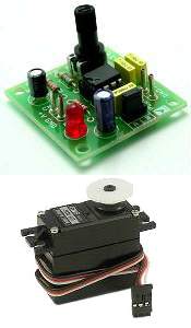
SERVO TESTER
This circuit can be used to manually turn a servo clockwise and anti-clockwise. By pushing the forward or reverse button for a short period of time you can control the rotation of the servo. It will also test a servo.Here is a photo of a kit from Cana Kit for $10.00 plus postage (it is a slightly different circuit) and a motor and gearbox, commonly called a "servo." The output shaft has a disk or wheel containing holes. A linkage or push-rod is fitted to a hole and when the disk rotates, the shaft is pushed and pulled. The shaft only rotates about 180° to actuate flaps or ailerons etc.
A pot can be used to control the position of the servo by using the following circuit. It produces a positive pulse between about 0.9 milliseconds and 2.1 milliseconds. The off period between pulses is about 40 milliseconds. This can be shortened by reducing the value of the 3M3 resistor.
SIREN 100dB
This is a very loud siren and if two or more piezo's are located in a room, the burglar does not know where the sound is coming from.A robber will not stay anywhere with an ear-piercing sound as he cannot hear if someone is approaching. It's the best deterrent you can get. The "F" contact on the piezo is "feedback" and is not needed in this circuit.
STEPPER MOTOR CONTROLLER TE555-1
The direction of rotation is determined by the FORWARD and REVERSE switches and the motor does not take any current when a switch is not pressed.
STUN GUN
This circuit produces a very high voltage and care must be used to prevent getting a nasty shock. The transformer can produce over 1,000v and the 8-stage multiplier can produce up to 20,000v
TICKING BOMB
This circuit sound just like a ticking bomb.
TILT SWITCH
The output is LOW at start-up due to the capacitor on pin 4. When the mercury switch closes, the output goes HIGH and remains HIGH until the reset button is pressed. This circuit is called a LATCH.
TOUCH SWITCH and TOUCH ON-OFF
The Touch Switch circuit will detect stray voltages produced by mains voltages and electrostatic build-up in a room. In the first circuit, pin 2 must see a LOW for the circuit to activate. If sufficient static voltage is detected by the plate, the chip will change state. If not, you will need to touch the plate and the 0v rail. In the second circuit, two touch plates are provided and the resistance of your finger changes the voltage on pin 2 or 6 to toggle the 555.
The circuit can be made 100 times more sensitive by adding a transistor to the front-end as shown in the diagram below:
TOY ORGAN
A circuit that produces 5 different sounds. OverviewThis circuit produces a tone according to the button being pressed. Only 1 button can be pressed at a time, that's why it is called a monophonic organ. You can change the 1k resistors to produce a more-accurate scale.
Schematic
Parts List
1x - NE555 Bipolar Timer
1x - 4.7K Resistor (1/4W)
4x - 1K Resistor (1/4W)
1x - 10K Potentiometer (1/4W)
1x - 10µF Electrolytic Capacitor (16V)
1x - 100nF Capacitor (16V)
1x - 8 Ohm Loudspeaker
1x - 9V Voltage Battery
TRAFFIC LIGHTS
Here's a clever circuit using two 555's to produce a set of traffic lights for a model layout.The animation shows the lighting sequence and this follows the Australian-standard. The red LED has an equal on-off period and when it is off, the first 555 delivers power to the second 555. This illuminates the Green LED and then the second 555 changes state to turn off the Green LED and turn on the Orange LED for a short period of time before the first 555 changes state to turn off the second 555 and turn on the red LED. A supply voltage of 9v to 12v is needed because the second 555 receives a supply of about 2v less than rail. This circuit also shows how to connect LEDs high and low to a 555 and also turn off the 555 by controlling the supply to pin 8. Connecting the LEDs high and low to pin 3 will not work and since pin 7 is in phase with pin 3, it can be used to advantage in this design.
4 WAY TRAFFIC LIGHTS
This circuit produces traffic lights for a "4-way" intersection. The seemingly complex wiring to illuminate the lights is shown to be very simple, in this diagram.
TRANSISTOR TESTER
The 555 operates at 2Hz. Output pin 3 drives the circuit with a positive then zero voltage. The other end of the circuit is connected to a voltage divider with the mid-point at approx 4.5v. This allows the red and green LEDs to alternately flash when no transistor is connected to the tester.
If a good transistor is connected, it will produce a short across the LED pair when the voltage is in one direction and only one LED will flash. If the transistor is open, both LED’s will flash and if the transistor is shorted, neither LED will flash.
TV REMOTE CONTROL JAMMER
This circuit confuses the infra-red receiver in a TV. It produces a constant signal that interferes with the signal from a remote control and prevents the TV detecting a channel-change or any other command. This allows you to watch your own program without anyone changing the channel !! The circuit is adjusted to produce a 38kHz signal. The IR diode is called an Infra-red transmitting Diode or IR emitter diode to distinguish it from a receiving diode, called an IR receiver or IR receiving diode. (A Photo diode is a receiving diode). There are so many IR emitters that we cannot put a generic number on the circuit to represent the type of diode. Some types include: CY85G, LD271, CQY37N (45¢), INF3850, INF3880, INF3940 (30¢). The current through the IR LED is limited to 100mA by the inclusion of the two 1N4148 diodes, as these form a constant-current arrangement when combined with the transistor and 5R6 resistor.
UNEVEN CLICKS
This circuit produces two clicks then a short space before two more clicks etc. Changing the voltage on pin, 5 via the diode, adjusts the timing of the chip.
UP/DOWN FADING LED
A Circuit that fades an LED on and off.Overview
These two circuits make a LED fade on and off. The first circuit charges a 100u and the transistor amplifies the current entering the 100u and delivers 100 times this value to the LED via the collector-emitter pins. The circuit needs 9v for operation since pin 2 of the 555 detects 2/3 Vcc before changing the state of the output so we only have a maximum of 5.5v via a 470R resistor to illuminate the LED.
Schematic
 Parts List
1x - NE555 Bipolar Timer
1x - LED (Red) 1x - 470 Resistor (1/4W)
1x - 33K Resistor (1/4W)
1x - 100µF Electrolytic Capacitor (16V)
1x - BC547 NPN Transistor
1x - 9V Voltage Battery
Do you validate your articles prior to post them ?
ReplyDeleteThe "UP/DOWN FADING LED" circuit overview states "These two circuits make a LED fade on and off" whereas there is only one circuit in the corresponding schematic section. Lucky for me I saw that circuit on the net somewhere else.
Don't be shy to give credit to the actual owners and designers and make sure the articles to copied are complete and usable.
Regards.
Superb...very help full for students and electronics hobbyist
ReplyDelete